How to Master Oscilloscope Triggering for Clear Waveforms
When you first power up an oscilloscope, the screen often looks like a chaotic mess of lines. The culprit? Triggering. Getting the trigger right is the key to freezing that elusive signal in a way that makes sense. Below, we unpack the basics, walk through the most common trigger modes, and share practical tips you can apply right away.
Why Triggering Matters
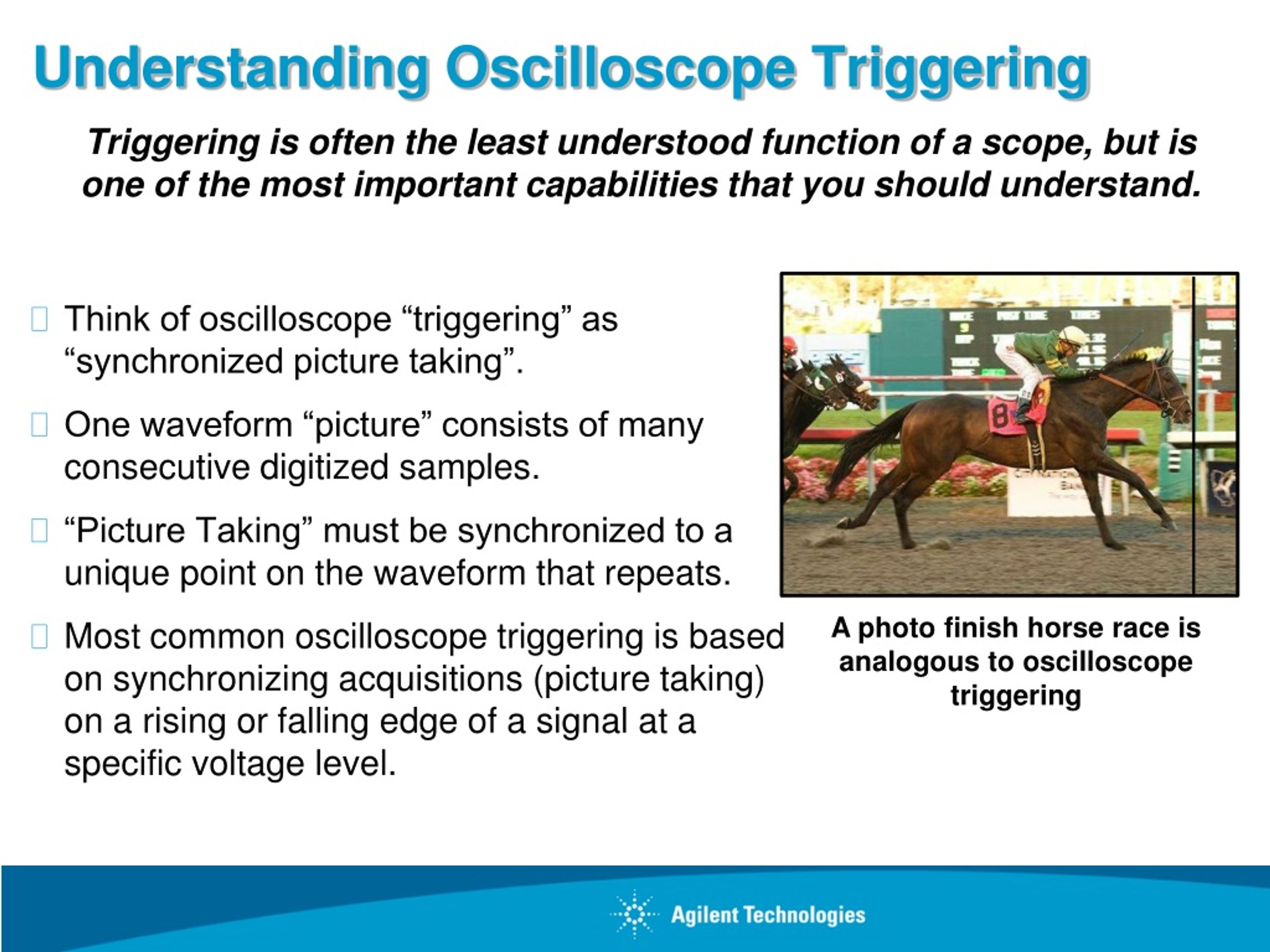
At its core, triggering tells the oscilloscope when to start sampling. Without a stable trigger point, each sweep begins at a random spot, and the waveform appears to drift or jitter. Think of it like trying to take a photo of a moving car without a flash—every picture looks slightly different.
The Fundamentals
1. Trigger Source
The source can be the channel you’re measuring, an external input, or even the oscilloscope’s own internal clock. Selecting the correct source ensures the device “knows” exactly which part of the signal to lock onto.
2. Trigger Level
This is the voltage threshold that the signal must cross to initiate a sweep. Adjusting the level up or down shifts the point on the waveform where the display stabilizes. A good rule of thumb: set the level near a prominent edge (rising or falling) for crisp results.
3. Trigger Slope
Most scopes let you choose rising, falling, or both. If you’re chasing a rising edge, pick “rising.” When a signal toggles quickly both ways, “both” can be handy, though it may introduce extra movement.
Common Trigger Modes
- Edge Trigger – The workhorse. Detects a voltage crossing a set level. Perfect for simple digital pulses and sine waves.
- Pulse Width Trigger – Fires when a pulse stays high or low longer (or shorter) than a specified time. Great for spotting glitches.
- Video Trigger – Optimized for video signals (e.g., VGA, HDMI). It aligns to the horizontal sync, making it easier to view picture quality.
- Runt Pulse Trigger – Captures pulses that never reach full amplitude, often a sign of a failing driver.
- Pattern Trigger – Monitors a specific digital bit pattern across multiple channels. Essential for debugging serial buses.
Step‑by‑Step: Setting Up a Stable Trigger
1. Connect your probe. Make sure the probe tip and ground clip are placed close together to avoid adding extra inductance.
2. Select the channel. Choose the channel that carries the signal you want to lock onto.
3. Switch to Edge mode. This is the default for most applications.
4. Set the trigger level. Drag the level marker on screen until the waveform stops sliding. If the display still wiggles, nudge the level a bit higher or lower.
5. Choose the slope. If you see the waveform still drifting, try the opposite slope. Sometimes a rising edge looks clean, but a falling edge is more stable, depending on noise.
6. Fine‑tune the horizontal scale. A slower sweep (more time per division) can make it easier to see whether the trigger is truly locked.
Advanced Tips for the Curious Engineer
- Use the “Holdoff” Setting. Holdoff tells the scope how long to wait after a trigger before looking for the next one. Increasing holdoff can suppress multiple triggers within a single cycle, smoothing out noisy waveforms.
- Combine Triggers. Some modern scopes allow “dual‑trigger” setups, where two conditions must be met simultaneously (e.g., a rising edge on channel 1 and a specific pulse width on channel 2).
- Employ the “Auto‑Set” Feature Sparingly. Auto‑set is convenient, but it often chooses a generic trigger that may not align with what you’re trying to debug.
- Mind Your Probe Compensation. An improperly compensated probe can alter the signal shape, making trigger adjustments feel like chasing a moving target.
When Things Go Wrong
Even seasoned users hit snags. Here’s a quick checklist:
- Is the ground lead forming a loop? Shorten it.
- Are you trying to trigger on a very low‑amplitude signal? Boost it with a pre‑amp or raise the vertical scale.
- Is there excessive high‑frequency noise? Add a small bandwidth filter.
- Did you inadvertently set the trigger to an external source you’re not using? Switch back to the channel source.
Practical Example: Capturing a UART Transmission
Suppose you need to view a 115200‑baud serial burst. Here’s a streamlined approach:
- Connect channel 1 to the TX line and set the probe to 10×.
- Switch the trigger mode to “Pattern” and define the start bit (low) followed by the first data bit.
- Set the trigger level just above the idle high voltage (often ~3.3 V) and choose a rising slope.
- Adjust the time base so that one bit spans roughly 5–8 divisions—this gives you room to see jitter.
- Enable “Holdoff” for roughly 5 µs to prevent retriggering on subsequent bits.
With these settings, the oscilloscope should freeze the UART frame, letting you inspect each bit’s timing and voltage level.
Wrapping Up the Essentials
Triggering isn’t magic; it’s a set of knobs and menus that, when understood, turn a fuzzy smear into a readable waveform. Start with the basics—pick the right source, set a clear level, and choose the appropriate slope. Then, as your needs grow, explore pulse width, video, and pattern triggers. Keep an eye on holdoff and probe compensation, and you’ll find that the oscilloscope becomes less of a mystery and more of a reliable partner in your troubleshooting toolbox.