How to Spot and Fix Common Injection Molding Defects
Injection molding is a cornerstone of modern manufacturing, yet even the most well‑engineered process can produce unwanted surprises. When parts come out with dents, cracks, or uneven surfaces, the culprit often lies in one of several familiar defects. Understanding the causes—whether they stem from material issues, machine settings, or design flaws—makes it possible to address them head‑on. In this guide we’ll explore the most frequent injection molding defects causes and solutions, give practical tips for prevention, and show how to spot problems before they become costly recalls.
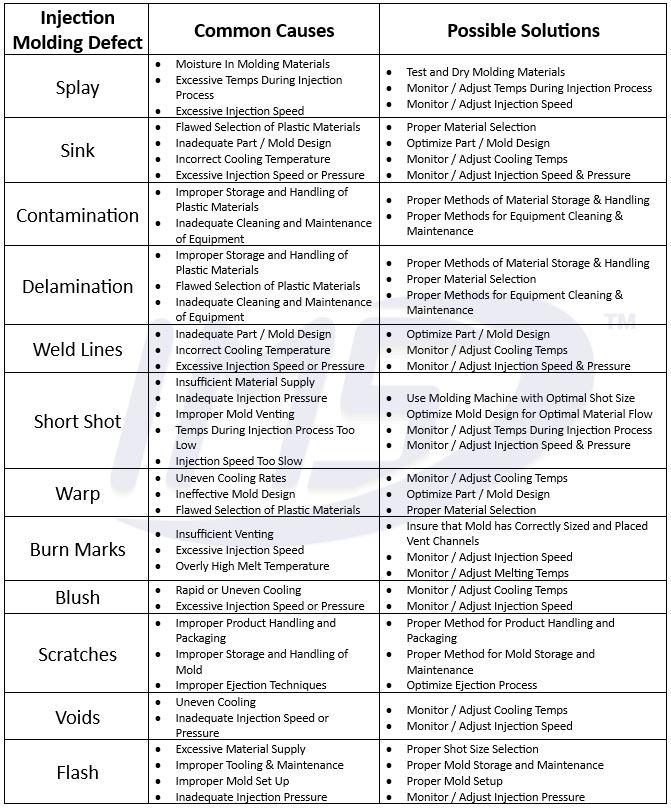
Common Causes of Injection Molding Defects
Before you can fix a defect, you first have to know what’s behind it. Here are the top reasons why parts fail to meet expectations:
- Material Problems – Low-quality resin, improper moisture content, or a mix of incompatible additives can all lead to poor flow or brittle final parts.
- Gate Design and Placement – Gates that are too close to one another or positioned in high‑stress areas often create sink marks, flow lines, and weld lines.
- Temperature Variations – Inadequate melt or mold temperature causes under‑extraction, voids, or scorching of the surface.
- Injection Pressure and Speed – Too high pressure can force air into the cavity, while too low pressure results in short shots.
- Ventilation Issues – Poor venting traps air, leading to voids and part distortion.
- Design Geometry – Thin sections, sharp corners, and sudden changes in wall thickness cause stress concentrations and warping.
- Machine Wear and Calibration – Out‑of‑calibration screws, worn bearings, or inconsistent clamp force introduce variability in every cycle.
- Process Timing – Incorrect hold time or cooling intervals let the part shrink unevenly or fail to solidify properly.
Key Solutions and Prevention Strategies
Once you know the root causes, you can adopt targeted fixes. Below is a roadmap for turning a problematic mold into a reliable production tool.
Material Management
- Store resin in climate‑controlled chambers to keep moisture levels below 0.02%.
- Use a consistent grade of plastic with a narrow melt flow range to ensure predictable viscosity.
- Implement a regular material audit—track supplier lot numbers and test each batch for viscosity and melt temperature.
Gate and Vent Optimization
- Select gate types (edge, point, or plug) based on part geometry; consider multiple gates for large cavities.
- Place gates where weld lines won’t be visible or critical—often in interior recesses or along the part’s centerline.
- Install properly sized vents (tubes or slots) opposite the gates to allow air to escape during filling.
Temperature Control
- Use dual‑temperature mold systems to maintain consistent wall and core temperatures.
- Employ real‑time sensors and feedback loops so that any drift in melt or mold temperature triggers an automatic adjustment.
- Pre‑heat the mold to a stable temperature before the first cycle of a new part to eliminate initial thermal shock.
Pressure and Speed Calibration
- Run a pressure sweep to find the sweet spot—enough to fill the cavity fully but low enough to avoid scarring.
- Set the injection speed so that the melt front moves steadily; too fast can cause turbulence and voids.
- Use a multi‑stage pressure profile: a rapid surge followed by a slower hold to counteract shrinkage.
Design Improvements
- Apply a 5‑degree draft angle to every face to ease ejection and reduce scarring.
- Maintain a minimum wall thickness of 1.5 mm (or as specified by the material) to avoid sink marks.
- Re‑evaluate any sharp radii; replace them with smoother transitions to reduce stress risers.
Machine Maintenance and Calibration
- Schedule monthly inspection of the screw, barrel, and clamp unit to catch wear before it affects quality.
- Use a calibrated load cell to verify that the clamp force remains consistent across cycles.
- Record machine logs; a sudden spike in cycle time often signals a mechanical issue.
Process Timing and Cooling
- Use a thermal simulation tool to determine the optimal cooling channel layout and timing.
- Adjust the hold time so that the part cools in a controlled manner—typically 1.5–2 × the cycle time.
- Include a final “release” phase where the part is pulled gently from the mold before it fully solidifies to reduce warping.
Inspection Techniques and Quality Control
Even with rigorous controls, defects can slip through. A solid inspection regime catches problems early.
Visual Inspection
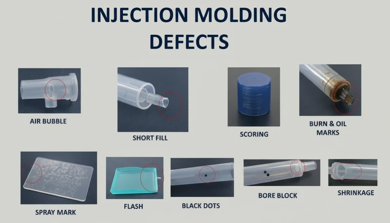
Look for obvious surface blemishes—scratches, burn marks, or uneven colors. A simple loupe can reveal fine cracks that would otherwise be missed.
Advanced Imaging
Computed tomography (CT) scans let you peer inside a part for voids or internal cracks without disassembly.
Tensile and Dimensional Testing
Measure tensile strength to confirm that the material meets specifications, and use a micrometer to ensure critical dimensions stay within tolerance.
FAQs
- What is a sink mark and how can it be avoided?
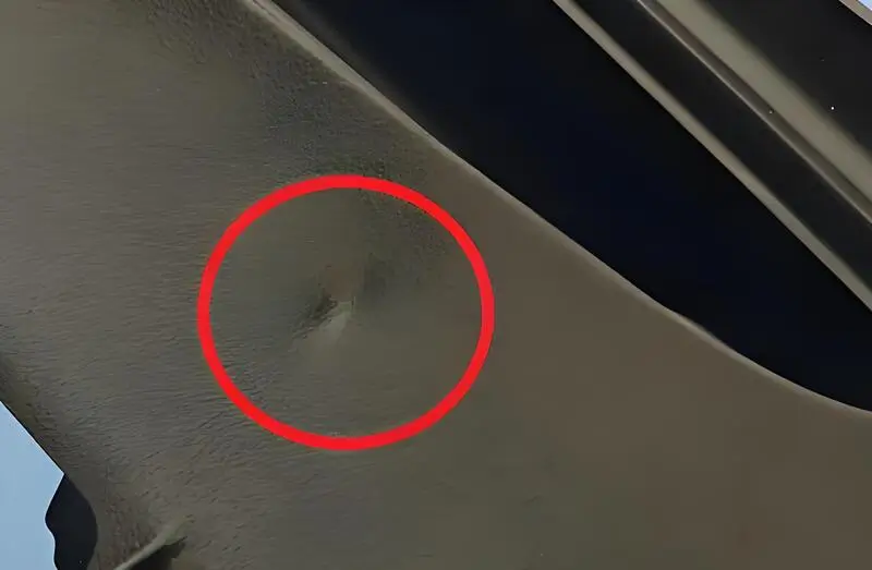
Sink marks are depressions that appear where the melt cools slower than the surrounding material, often due to thick sections or inadequate venting. They can be mitigated by redesigning the part to reduce thickness variations, adding vents, or increasing the holding pressure during injection. - How does moisture in resin affect the final part?
Moisture leads to steam formation during heating, creating bubbles or porosity. This not only weakens the part but also causes surface scuffs and burn marks. - Can I change the gate type mid‑production?
It’s best to plan gate placement before committing to a large run. Switching gate types requires mold modification, which can be costly and time‑consuming. - What is the ideal cycle time for a 200 g part?
Cycle time depends on part geometry, material, and machine capabilities, but a typical range is 10–30 seconds. Shorter cycles increase throughput, while longer ones improve part quality.