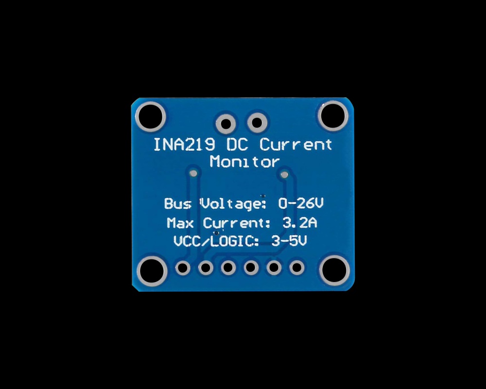
How to Simplify Power Monitoring with the TI INA219
When you’re building a battery‑operated device or tweaking a power‑hungry board, knowing exactly how much voltage and current flow through your circuitry can feel like a secret weapon. The Texas Instruments INA219 shunt‑monitor is one of those tools that turns guesswork into precise data without demanding a PhD in analog design.
What Makes the INA219 Stand Out?
The INA219 is a low‑power, I²C‑compatible integrated circuit that measures both shunt voltage and bus voltage, then calculates current, power, and even accumulated energy. Its key selling points are:
- Wide measurement range: up to 26 V bus voltage and ±3.2 A shunt current.
- High resolution: 0.1 mV shunt‑voltage steps translate to micro‑ampere current precision.
- Simple interface: just two I²C lines and a handful of configuration registers.
- Built‑in calibration: a single 16‑bit register lets you align the chip with any shunt resistor you choose.
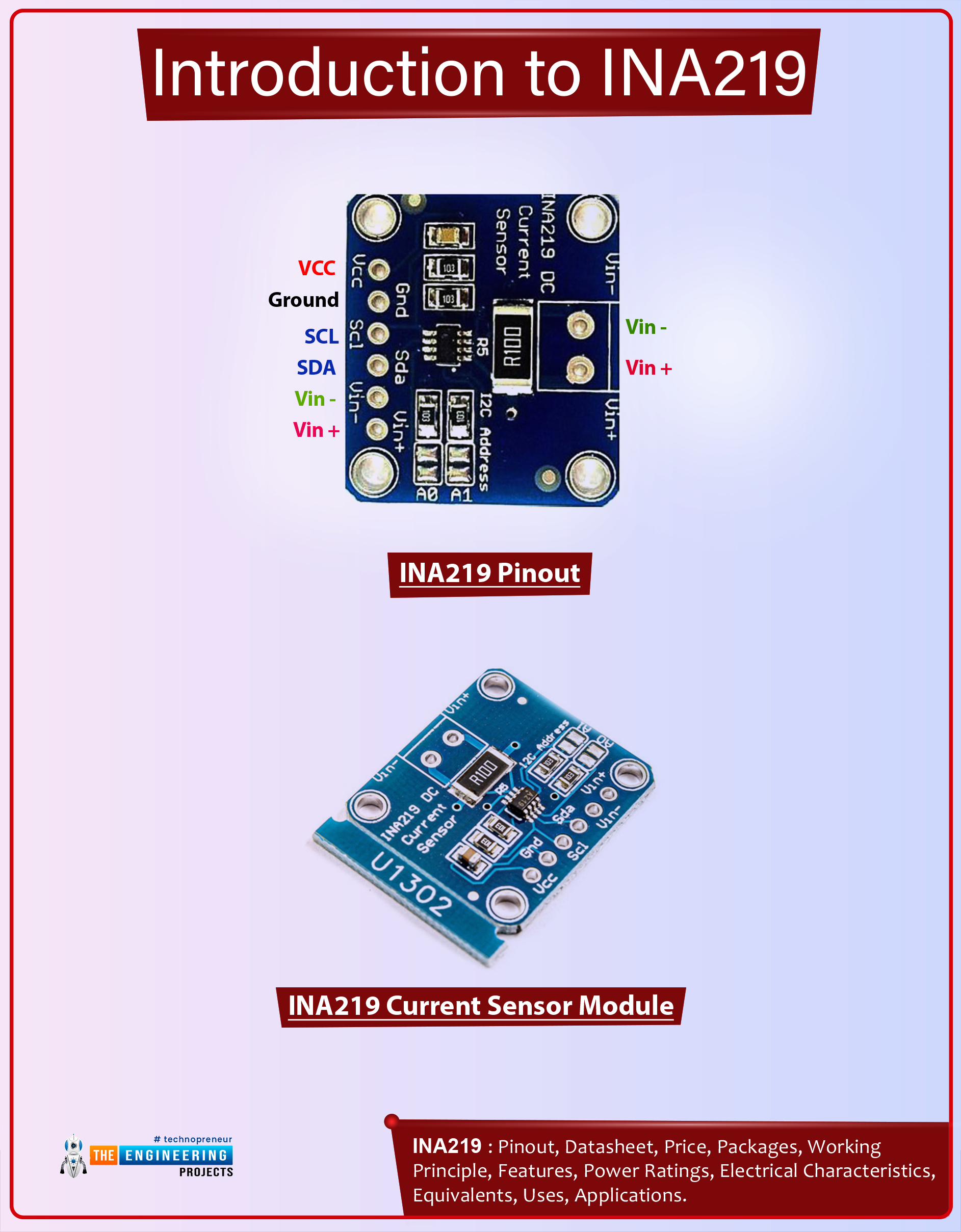
Getting Started: Wiring the INA219
Even a first‑time hobbyist can hook up the chip in under ten minutes. Here’s the minimal setup:
- Connect VCC to 3.3 V or 5 V (both are fine).
- Attach the SDA and SCL lines to your microcontroller’s I²C bus, pulling them up with 4.7 kΩ resistors.
- Place a precision shunt resistor (typically 0.1 Ω to 0.01 Ω) between the V‑ and V+ terminals.
- Route the bus voltage pin (VBUS) to the point you want to monitor, such as the output of a regulator.
Once powered, the chip immediately begins sampling. The only thing left is to tell it how big your shunt is.
Calibrating for Accurate Readings
The calibration register is where the magic happens. TI provides a straightforward formula:
Calibration = 0.04096 / (Current LSB × RSHUNT)
Pick a Current LSB that comfortably spans your expected maximum current—say, 1 mA for a 2 A maximum. Then plug in your shunt value, compute the register value, and write it over I²C.
Because the INA219 performs all the math internally, you’ll get back current in milliamps, power in milliwatts, and energy in millijoules with just a few register reads.
Practical Tips for Real‑World Use
- Watch the bus voltage limit. The device will saturate above 26 V, so if you’re measuring a higher rail, add a simple voltage divider before the VBUS pin.
- Mind the shunt heating. Even a 0.01 Ω resistor can get warm at several amps—choose a resistor with adequate power rating.
- Use averaging. The INA219 offers a programmable conversion time and averaging mode; longer times smooth out noise at the cost of slower updates.
- Don’t forget grounding. A solid common ground between the INA219 and your MCU prevents false readings caused by ground bounce.
Reading Data with Arduino (Example Code)
If you’re using an Arduino, the Adafruit_INA219 library wraps the I²C commands nicely. A quick sketch might look like this:
#include <Wire.h>#include <Adafruit_INA219.h>
Adafruit_INA219 ina219;
void setup() {
Serial.begin(115200);
ina219.begin();
ina219.setCalibration_32V_2A(); // preset for 0.1Ω shunt
}
void loop() {
float busV = ina219.getBusVoltage_V();
float shuntV = ina219.getShuntVoltage_mV() / 1000.0;
float current = ina219.getCurrent_mA() / 1000.0;
float power = ina219.getPower_mW() / 1000.0;
Serial.print("Bus: "); Serial.print(busV); Serial.print(" V ");
Serial.print("Current: "); Serial.print(current); Serial.print(" A ");
Serial.print("Power: "); Serial.print(power); Serial.println(" W");
delay(1000);
}
The library handles the register math, leaving you to focus on what the numbers mean for your design.
Beyond the Basics: Advanced Applications
Once you’ve mastered simple voltage‑current monitoring, the INA219 can become a cornerstone of more sophisticated systems:
- Dynamic power budgeting. Shut down peripherals when the measured power exceeds a threshold.
- Battery health tracking. Integrate power over time to estimate remaining capacity.
- Fault detection. Spot sudden spikes in current that could indicate a short or component failure.
Because the chip talks I²C, you can daisy‑chain several INA219 units on the same bus, each with a unique address. This makes multi‑rail monitoring on a single board surprisingly easy.
Common Pitfalls and How to Avoid Them
Even with a straightforward datasheet, a few missteps can trip you up:
- Wrong shunt value. Using a resistor that’s too large will limit measurable current; too small and you’ll lose resolution.
- Ignoring temperature effects. Both the shunt resistance and the INA219’s own offset drift with temperature; for critical applications, calibrate at operating temperature.
- Overloading the I²C bus. If you poll the chip too fast while sharing the bus with other slow peripherals, you may see missed reads. Throttle your sample rate accordingly.
Wrapping Up
The INA219 packs a lot of functionality into a tiny package, and with just a handful of connections it starts delivering real‑time power data you can trust. Whether you’re fine‑tuning a solar charger, protecting a motor driver, or just curious about how much juice your prototype draws, the chip gives you the numbers you need—without the headache of manual calculations.
All that’s left is to solder the shunt, pull the I²C lines high, write a few lines of code, and let the INA219 do the heavy lifting. In the world of embedded power design, that’s about as easy as it gets.