How to Wire an EPS Torque Sensor: A Step‑by‑Step Guide
Electric power steering (EPS) relies on a torque sensor to feel the driver’s input and translate it into precise steering assistance. Getting the wiring right is crucial—not only for smooth operation but also for avoiding costly diagnostic trips. Below is a practical walkthrough that covers everything from the basics of sensor signals to the final verification on a bench or in the vehicle.
What Makes an EPS Torque Sensor Tick?
The sensor is essentially a small, rugged transducer that measures shaft twist. Most modern units output a variable‑resistance or diagnostic‑ready voltage signal that the EPS control module interprets. Understanding the signal type determines how you’ll connect the wires.
- Resistive (potentiometer) output: two wires form a voltage divider; resistance changes with torque.
- Hall‑effect voltage output: three‑wire configuration (V+, GND, Signal) provides a linear voltage proportional to torque.
- Digital (CAN‑based) sensors: require a high‑speed data line plus power and ground, but they’re far less common in retrofit projects.
Essential Tools and Materials
- Multimeter (capable of resistance and voltage measurement)
- Soldering iron with fine‑tip
- Heat shrink tubing or electrical tape
- Wire strippers and crimpers
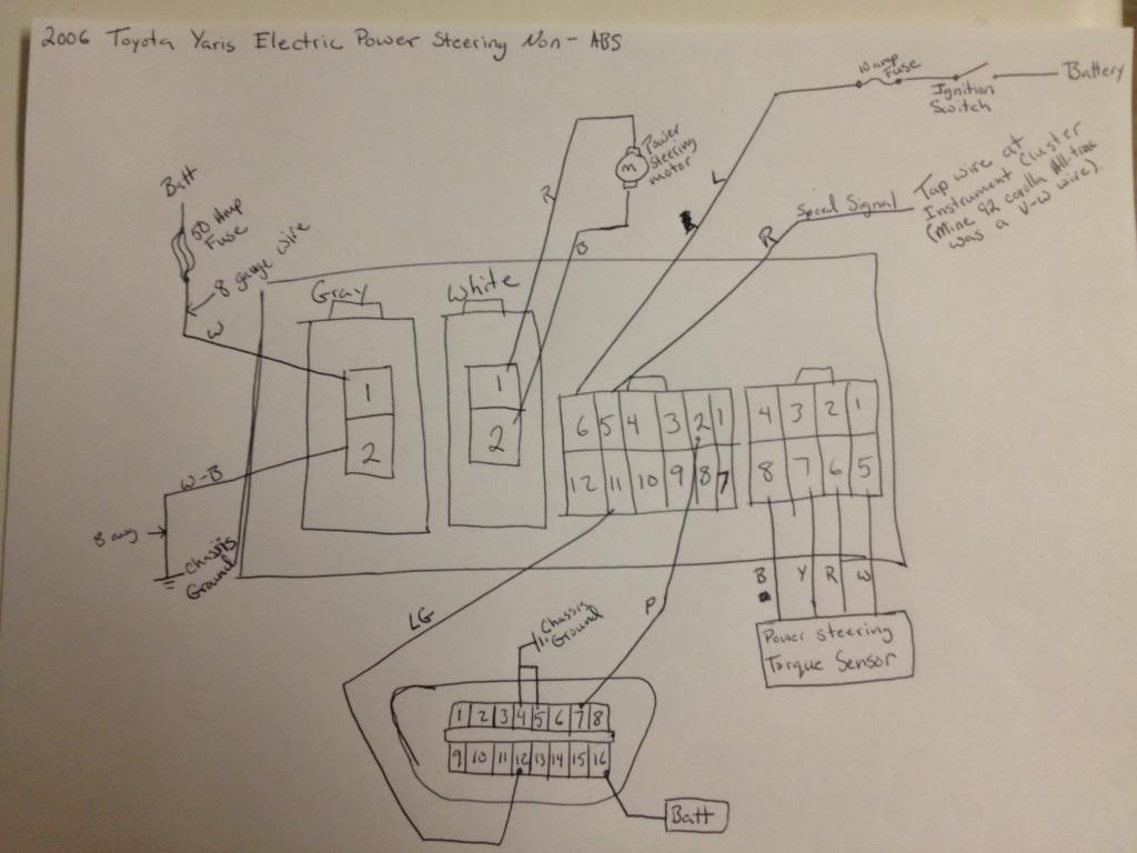
- Factory‑service wiring diagram (or a reliable aftermarket schematic)
Step 1: Identify the Wire Colors and Functions
Most manufacturers follow a standard color code, but it’s not universal. A typical three‑wire Hall‑effect sensor might use:
- Red: +5 V power
- Black: Ground
- Green (or yellow): Signal
If your sensor uses a resistive output, you’ll see only two wires—usually one for power/ground and another for the variable resistance feed.
Step 2: Verify Sensor Continuity Before Installation
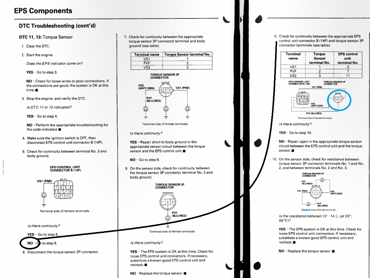
Connect the multimeter’s leads to the sensor leads and check:
- Resistance between power and ground: should read near zero (just the wire’s own resistance).
- Signal continuity: for a Hall sensor, you should see a steady voltage (around 2.5 V) when power is applied and the shaft is at rest.
If the values are out of spec, it’s better to replace the sensor now than troubleshoot later.
Step 3: Prepare the Vehicle Harness
Locate the EPS control module—usually tucked near the steering column or in the engine bay. Using the wiring diagram, trace the sensor’s dedicated connector. Clean any corrosion and trim the wires to a manageable length; remember, excess slack can rattle and lead to premature failure.
Step 4: Solder, Secure, and Insulate
When joining the sensor wires to the harness:
- Strip about 3 mm of insulation from each end.
- Twist the corresponding wires together, then apply a quick solder joint. A small amount of solder is enough—too much can create a stiff joint that cracks under steering vibration.
- Slide heat‑shrink tubing over the joint before soldering, then shrink it afterward for a clean seal.
If you prefer crimp connectors, choose high‑quality solder‑less terminals; they’re quicker but must be pressed firmly to avoid micro‑movement.
Step 5: Power‑Up and Test the Signal
Reconnect the battery and turn the ignition to the “ON” position (do not start the engine yet). Using the multimeter set to DC voltage, probe the signal wire while rotating the steering wheel gently:
- Signal should rise as you turn left and fall as you turn right.
- Typical range for a 5 V Hall sensor is roughly 1.5 V to 3.5 V.
- Any sudden jumps or flat lines suggest a wiring fault or sensor defect.
Step 6: Calibrate the EPS Module (If Needed)
Some EPS systems require a quick calibration after sensor replacement. This is usually done through the vehicle’s diagnostic interface (e.g., OBD‑II) by selecting “Steering Calibration” and following the prompts. The process generally involves turning the wheel from lock‑to‑lock while the module records the sensor’s full range.
Common Pitfalls and How to Avoid Them
- Mixed‑up wire colors: double‑check with the service manual; never assume.
- Loose connections: a vibrating joint can intermittently disconnect, causing the EPS light to flash.
- Incorrect voltage supply: feeding a Hall sensor with 12 V instead of 5 V will fry the output stage.
- Ground loops: ensure the sensor ground shares the same reference point as the EPS module to prevent noise.
What to Do If the EPS Light Stays On
Even with perfect wiring, the control module may still flag an error. In that case:
- Re‑scan the system for trouble codes; look for sensor‑related DTCs (e.g., C1234).
- Inspect the connector pins for bent or missing pieces.
- Measure the sensor’s resistance or voltage again—sometimes a subtle shift occurs after the module powers up.
- If everything checks out, consider resetting the module by disconnecting the battery for five minutes, then re‑initializing the calibration.
Final Thoughts on Reliability
A well‑wired EPS torque sensor can last the life of the vehicle, provided you respect torque limits during installation and keep the wiring away from moving parts. Periodic visual checks during routine service—especially after suspension work—can catch early wear before it becomes a safety issue.